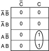
K Map Of Full Adder. Full addition requires carry-in and carry-out bits. Using K-map in Full Adder Circuit. This can be derived by the use. It is used for the purpose of adding two single bit numbers with a carry.. Here are a number of highest rated Full Adder K Map pictures on internet. K Map Of Full Adder

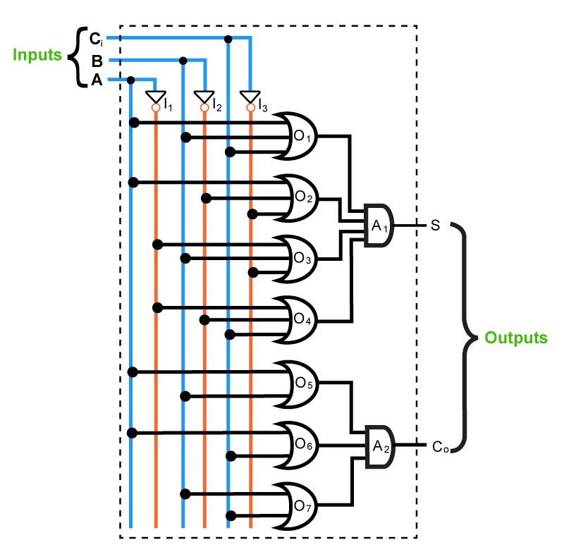
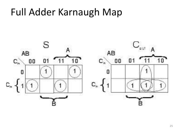
Hence, from K-maps, Binary Parallel Adder.
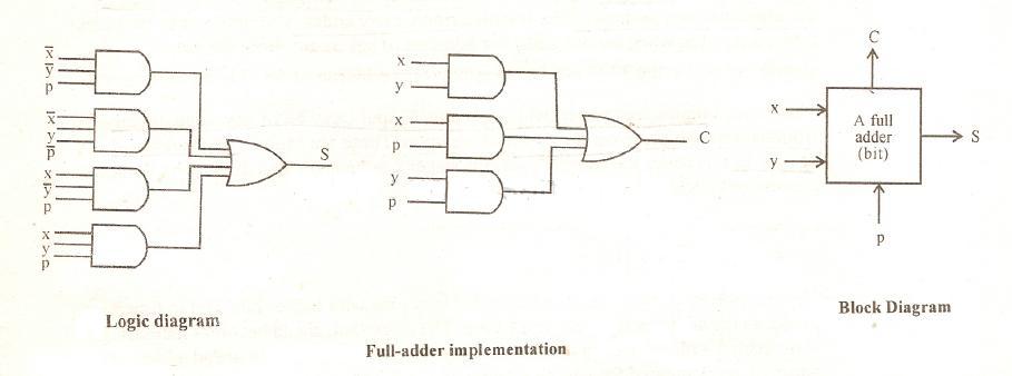
Simply, a circuit in which different types of logic gates are combined.
Half Adder Full Adder | Gate Vidyalay
The Karnaugh Map Boolean Algebraic Simplification Technique - Technical ...
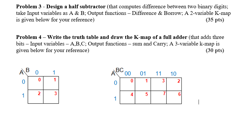
Full Subtractor Truth Table K Map | Decoration Items Image
Full Subtractor Truth Table K Map | Decoration Items Image
Binary Adder Half and Full Adder | Electrical4U
Lec20
Binary Adder Half and Full Adder | Electrical4U
The Karnaugh Map Boolean Algebraic Simplification Technique - Technical ...
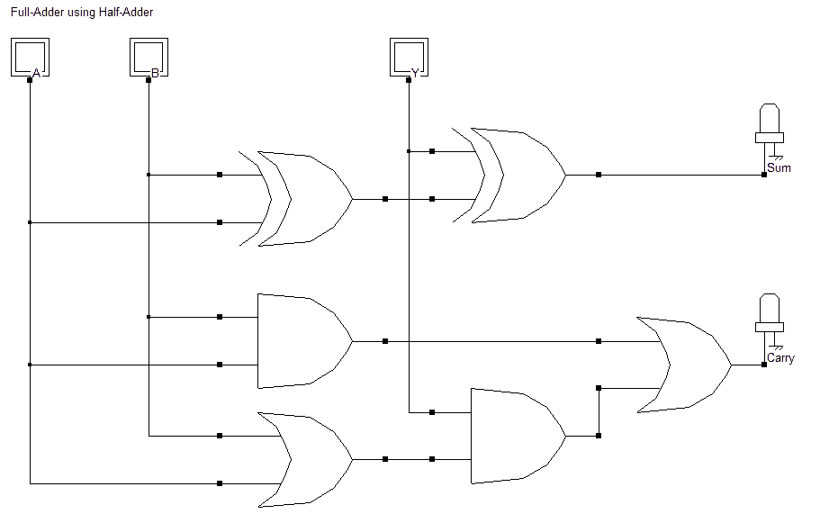
Half Adder - Full Adder, truth table, Logic circuit - Electronics Club
A 2-bit adder-subtractor circuit block diagram 6m Jun2006 | Computer ...
PPT - Number Representation and Logic Design PowerPoint Presentation ...

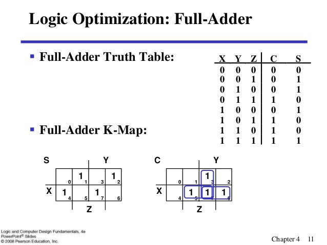
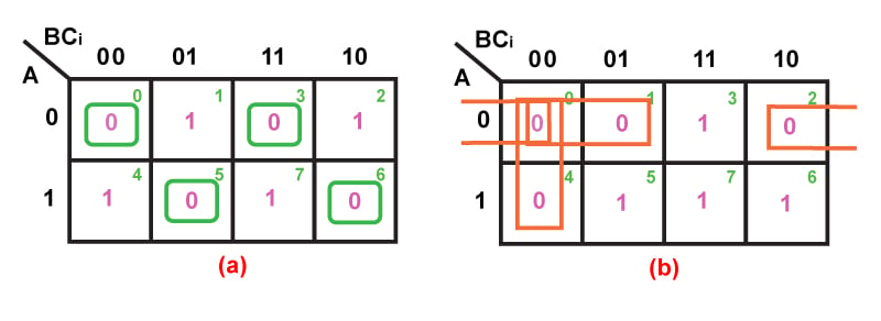
What is K-map and how to design full adder circuit simplifying SOP ...
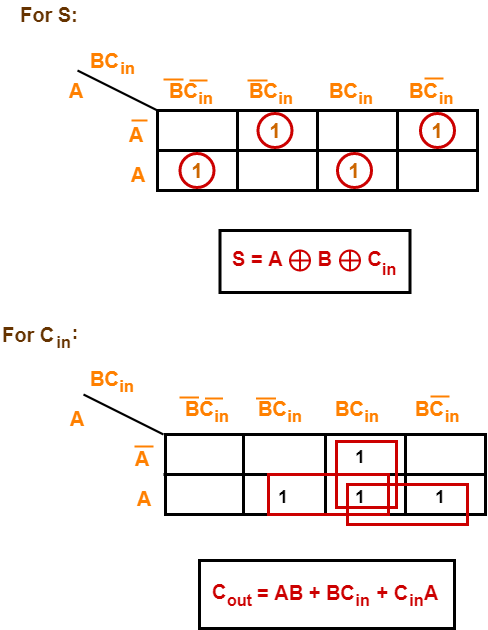
K Map Of Full Adder ADDER : IN ELECTRONICS AN ADDER IS DIGITAL CIRCUIT THAT PERFORM ADDITION Half Adder and Full Adder using K-Map. The output carry is designated as C-OUT and the normal output is designated as S which is SUM. Draw K-maps using the above truth table and determine the simplified Boolean expressions- Also Read.